Aerofoil Lab
A brief look at wind tunnel testing of an aerofoil, with some personal reflections.
June 20, 2025 - Written by Luke Beasley.
Going into second year, I already had some knowledge of how lift and stall worked with an aerofoil, and how high lift devices were employed on real aircraft to improve flight characteristics during landing and takeoff. However, this lab exercise (and subsequent written report) really helped bridge the gap in my mind between the real-world usage of aerofoils and high lift devices, and the aerodynamic theory that makes them tick.
Some Background
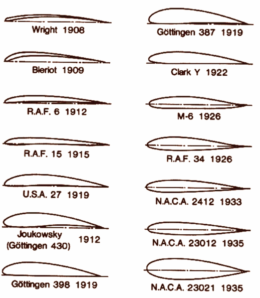
Aerofoils are specialised shapes that form the cross-section of an aircraft wing. Their shape generates lift due to a pressure difference created between the top and bottom surface of the aerofoil as it passes through air. Aerofoils have been continuously developed since their inception - here you can see some early 20th century improvements [1].
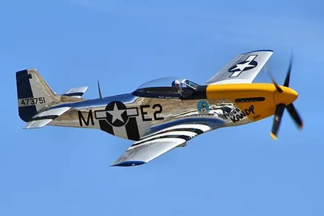
Aerofoil research was of critical importance to improvements in both civilian and military aircraft, offering improved performance in areas such as range or fuel burn. Research became formalised in the United States under NACA, which used extensive wind tunnels to perfect aerofoil designs in the interwar period. Then, in the Second World War, a NACA-developed “laminar flow” aerofoil was first used on the P51 Mustang - a revolutionary fighter aircraft with superior range and speed. Even on long-distance escort missions, this fighter held the edge over its Axis counterparts thanks to its scientifically engineered aerofoil, which encouraged laminar airflow over the whole wing area, greatly improving its performance [2].
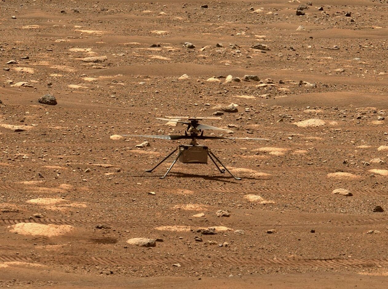
Nowadays, wind tunnel testing is still paramount in research and development - advanced facilities can even simulate the atmospheric conditions of other planets, allowing for pioneering operations on Mars such as that demonstrated by NASA with Ingenuity. With aerofoil-shaped rotors specifically tuned for the atmosphere of Mars, this little spacecraft became the first aircraft to achieve flight on a celestial body other than our own - something it repeated for a total of 72 flights [3].
The Lab
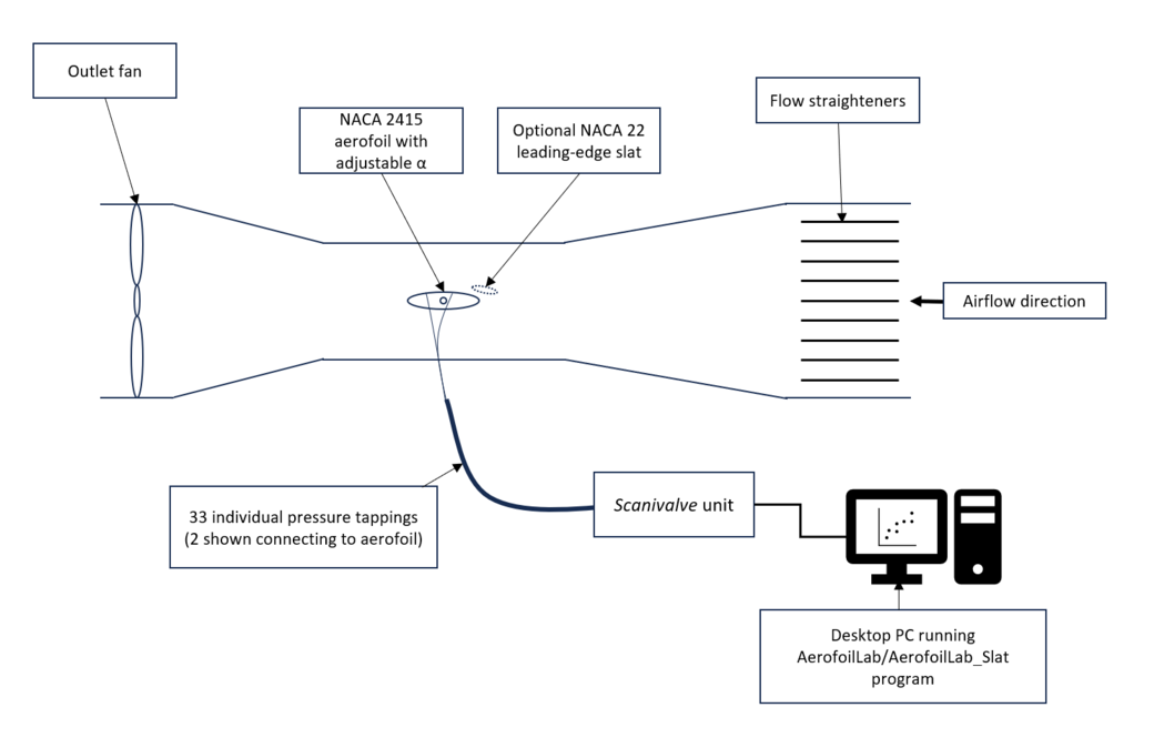
I’ll do you a favour and skip straight to the physical lab, missing out the underlying theory that needed to be covered in the report (of which there was a lot!). Here was the setup we used (I’m quite proud of this diagram - turns out Powerpoint really does have its uses). You can see that we could add an optional leading edge slat to improve lift at high angles of attack (AOA), a technique ubiquitous in modern aircraft. We could adjust the AOA of the aerofoil(s), and read the pressure at various points across the main aerofoil surface.
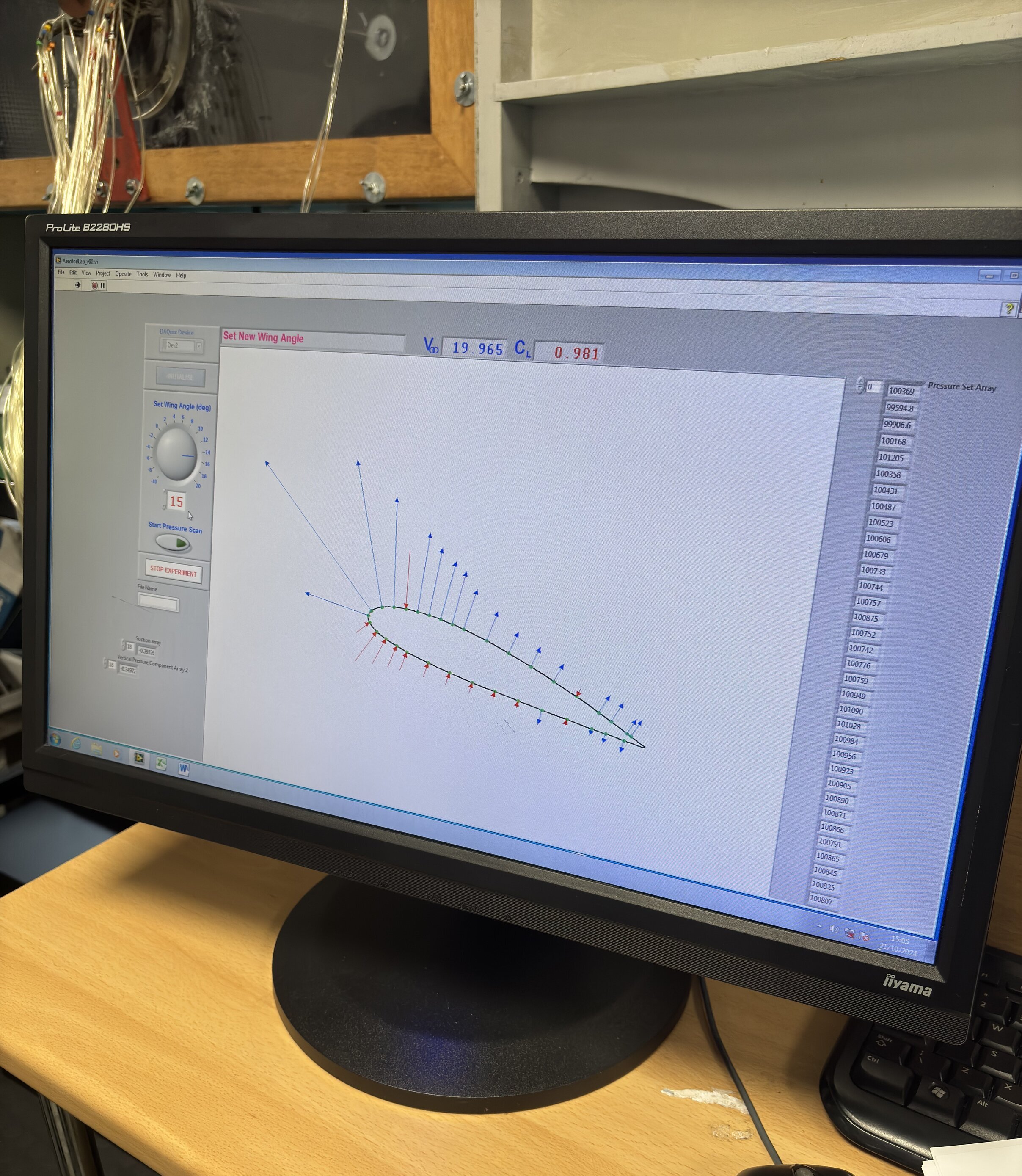
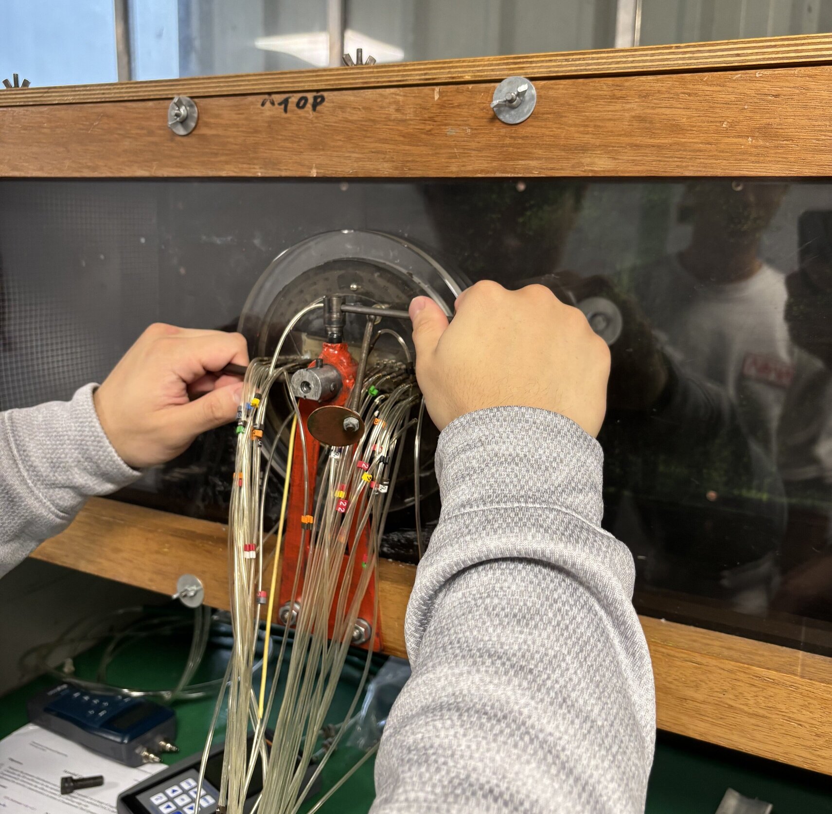
Here’s a shot of the setup mid-adjustment - I had the fun job of setting the AOA for each run on the computer, hitting run, and then shouting the output across the lab to be written down (what’s a spreadsheet?). You can see the computer setup for this in the top image. A MATLAB script on the computer integrated across the pressure readings to work out the coefficient of lift for the aerofoil in a given AOA - a key dimensionless parameter.
The setup was really interesting, with the wind tunnel being large and noisy, taking up most of a room. It’s exciting to think about what building-sized wind tunnels can do!
Results
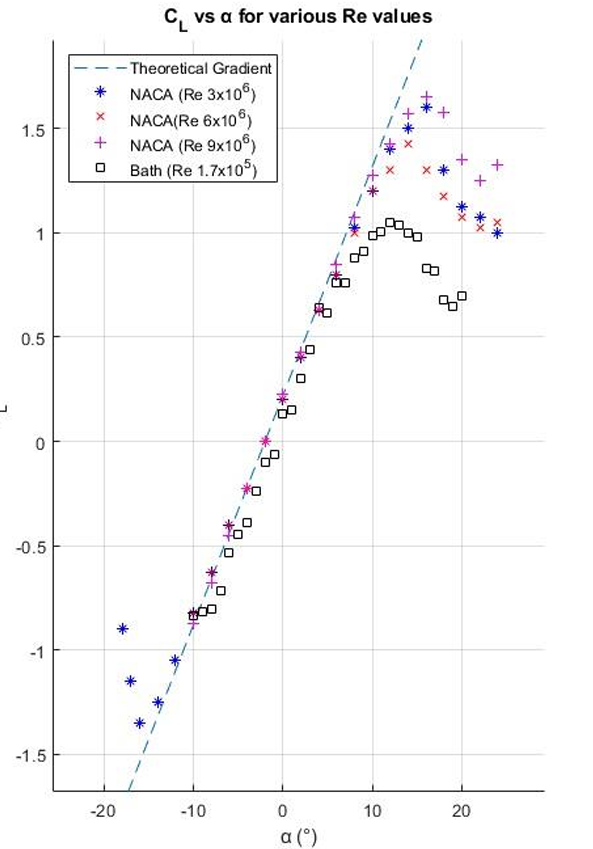
Here you can see how the lift performance of the aerofoil varied compared to theory and NACA experiments. Note the NACA data used higher Reynolds numbers in their experiments, which increased the AOA needed for the aerofoil to stall as a lower Reynolds number indicates more turbulent flow. For instance, later calculations showed that an airliner in flight would experience a Reynolds number approximately 100 times greater than that used in our wind tunnel - however to model this Reynolds number would be vastly more expensive, needing much faster airflow.
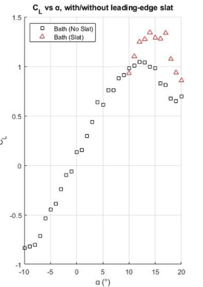
This image shows the effect of adding a leading edge slat ahead of the aerofoil. You can clearly see that the lift performance of the aerofoil is greatly improved, delaying stall to higher AOAs by injecting high velocity airflow onto the upper surface of the aerofoil - this is why real aircraft use leading edge slats at takeoff and landing, to increase lift at lower speeds. We also found that the pressure distribution across the aerofoil varied significantly with increasing AOA, with a boundary separation point visible at the stall AOA. Use of a leading edge slat more or less restored the aerofoil’s pressure distribution to its original, 0 AOA state.
Sources of Error
Aerofoil AOA was visually set, introducing parallax error. While the pressure monitoring unit could have had a systemic error, it was used for each pressure tapping so the error would be consistent across each. One of the leading-edge suction surface tappings was faulty, and produced a high-pressure readout each AOA. You can actually see this in the top image - this likely reduced the lift coefficient of the aerofoil for each test. Resolution was limited by the number of pressure tappings – increasing the number of measurement points would have improved the quality of pressure distribution readouts and aided stall analysis. Other potential errors included that, over time, the wind tunnel could slow down due to resistive heating, and despite flow straighteners, the open-loop nature of the wind tunnel (it recirculated air through the room it was sat in) could introduce disturbances to the airflow (for instance, if someone moved near to the inlet or exhaust).
Conclusions
With technical conclusions aligning with existing theory, I’d prefer to use this section to record my thoughts on the experiment. I really enjoyed it - this was my first hands-on experience with a wind tunnel, and one thing I definitely realised is that while aerodynamic theory is an excellent predictor of performance or results, the wind tunnel is a fantastic (and essential) component in validating your maths or Computational Fluid Dynamics (CFD), as airflow is just so difficult to model. Another thing I find quite fascinating is the non-dimensional aspect of the wind tunnel - by setting certain parameters correctly, such as air temperature and speed, you can effectively test a scaled-down prototype of your design (which could be huge/expensive/both) - and this is commonly done in industry. I hope that in the future wind tunnel testing (or its results) might become part of my work - it would definitely be awesome to work on a super/hypersonic wind tunnel to test some seriously fast stuff.
References
- Gelzer, C., 2015. 100 Years [Online]. NASA Armstrong Flight Research Center: NASA. Available from: https://www.nasa.gov/wp-content/uploads/2021/02/NACA_100_X-Press.pdf [Accessed 20/06/2025]
- [Author not available], 2023. The P-51 Mustang: The Crown Jewel of World War II Aviation [Online], Acesinaction.blog. Available from: https://acesinaction.blog/2023/06/08/the-p-51 mustang-the-crown-jewel-of-world-war-ii-aviation/ [Accessed 30/10/2024]
- [Author not available], 2024. Ingenuity Mars Helicopter [Online] NASA. Available from: https://science.nasa.gov/mission/mars-2020-perseverance/ingenuity-mars-helicopter/ [Accessed 31/10/2024]