Air Jet Lab
Analysis of jet exhaust, demonstrating the capability (and shortcomings) of Fluid Mechanics theory.
June 23, 2025 - Written by Luke Beasley.
In this first year lab exercise, we studied the exhaust of an electric air jet - this was a good intro to practical Fluid Mechanics, and highlighted key phenomena that theory just couldn’t predict.
Some Background
If you’ve ever been on an airliner to travel abroad, its almost certain you’ll have relied on jet turbines to get from point A to point B smoothly and safely. You’ll have seen them attached under the wings (or less commonly at the back of the aircraft) - these jet turbines generate thrust by discharging fast-moving gas through a complex sequence of intake, compression, combustion, and exhaust (suck, squeeze, bang, blow may be a little more memorable, if a bit more crude).
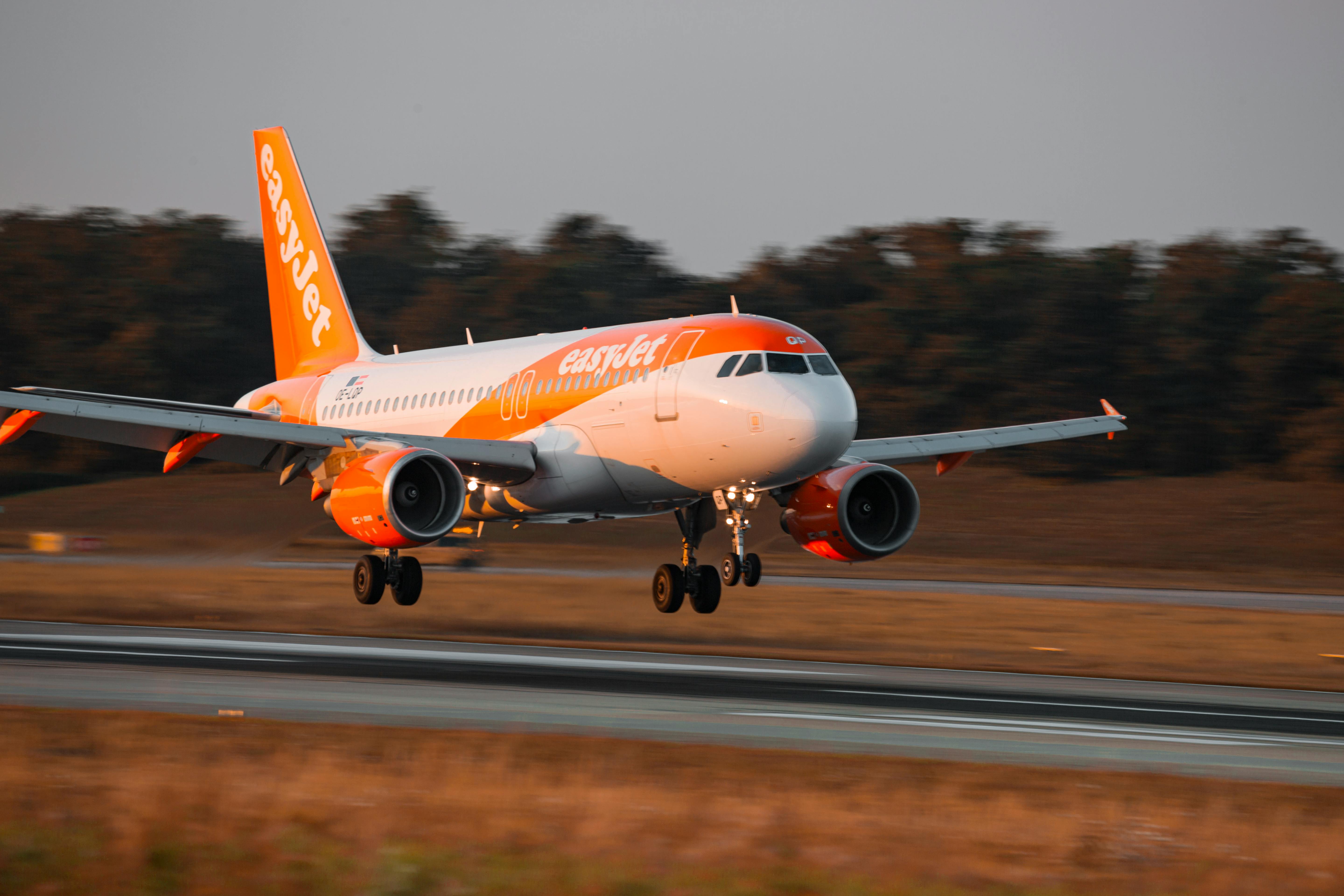
However, it turns out that jet turbines are found in many more places than you might expect. I’ll never forget how confused (and slightly embarrassed) I was when, as a very young passenger, I confidently told the captain in the cockpit that his aeroplane (like the one above [1]) had two jet turbines, only to be told it had three! As it turns out, an additional jet turbine was situated in the tail, intended to provide power to the aircraft on the ground amongst other uses - a very common feature on aircraft. Variations to this design can be found onboard ships, and in power plants for the same purpose. However, this lab focussed on the previously mentioned use case of jet turbines - to move things using high energy exhaust air. Studying the exhaust of a small electric air jet would be a great way to put Fluid Mechanics theory to the test.
Experimental Setup
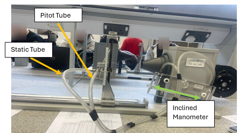
Here’s the setup we used to take a look at what’s going on in a jet turbine exhaust. You can see the air jet device on the right hand side, with a pitot-probe setup to its left.
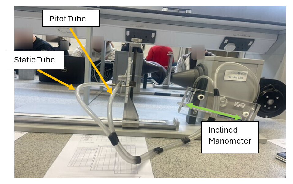
The pitot-probe device samples the dynamic and static pressure in the exhaust (see below). By recording the water level on the inclined manometer (which compared the two exhaust pressures) it was straightforward to find the flow velocity using Bernoulli’s Principle.
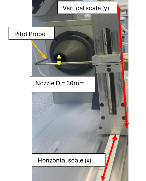
The pitot probe could be translated around within the exhaust area of the jet, allowing for analysis.
Results/Discussions
Here were the primary findings of the experiment:
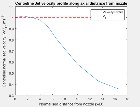
- With increasing distance from the exhaust nozzle, airflow speed increased within a ‘core region’, before reducing due to interaction with ambient (static) air. You can see this below - note VE is the initial exhaust velocity. The initial increase in airflow speed could be due to a focusing effect caused by the nozzle.
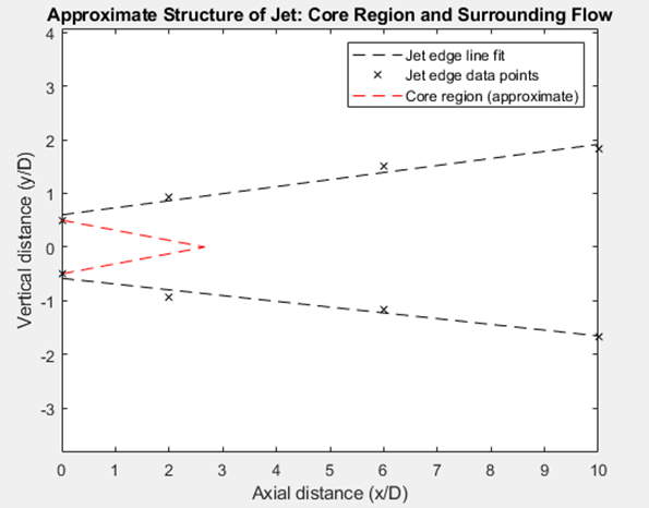
- With increasing horizontal or vertical distance from the jet centreline, airflow velocity predictably reduced to zero - the distance from the centreline at which this occurred was recorded as the jet edge. Interestingly, the jet edge expanded more rapidly (larger angle) on the upper surface of the jet exhaust than the lower, due to the ground effect and obstructions caused by the table, pens, and other objects underneath the jet exhaust. This is quite hard to see on the below image as this variation in angle was only approximately 1.5 degrees.
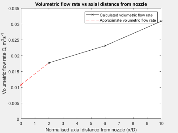
- The volumetric flow rate of the jet exhaust increased with distance - this is implied in the image above but was also calculated by integrating velocity values across the air flow. This was due to the entrainment of static air surrounding the jet flow, expanding the volume of the jet flow with increasing distance.
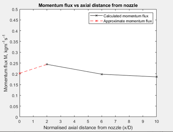
- In a very satisfying way, energy is conserved despite the increase in volumetric flow rate. See the momentum flux vs distance graph below - ignoring the second data point which is likely anomolous (see Sources of Error) momentum flux stays constant due to the Law of Conservation of Momentum. Despite additional airflow joining the jet exhaust, the overall velocity of the airflow reduces with distance as faster airflow transfers energy to slower or static air, giving no overall change in momentum.
Sources of Error
There were some key sources of error to be considered in this experiment - for instance, the pitot-probe cannot accurately measure velocity at a point as the static and dynamic pressure are not measured in the same plane. However the error in reading the manometer scale was much more significant - getting the water level off by one millimeter would influence the results by a huge amount, especially at small manometer readings - and I don’t have the best eyes to start off with! It didn’t help that we had to make plenty of measurements, constantly glancing between the manometer, the pitot-probe position gauges, and the worksheet. Obviously, disturbances like drafts, students moving in the room, and other obstacles could also have influenced the jet exhaust, as it was quite low velocity to begin with.
Reflections
This lab was quite enjoyable - I particularly enjoyed seeing where the theory held up and where it didn’t, and learning about phenomena like ground effect and entrainment that you just don’t come across when working the usual Fluid Mechanics equations. As part of the coursework, we had to submit a thorough report - and looking back from over a year later I can see so much I would’ve done differently! Not taking screenshots of MATLAB graphs, improving my LaTeX formatting, and just improving the overall flow of the report amongst many other things - its good to reflect and see how far I’ve come since this piece of work. I believe I scored between a 2:1 and a 1:1, but I’m unsure of the final mark. I’ll update this if I can find it. Overall, I’m pleased with how this coursework panned out, and it would help build up key concepts that would be crucial in the Aerofoil and Steam labs of year two. I’d be excited to work on testing like this in future - I’m sure its much more sophisticated and nuanced in industry, and it would be great to find out more.
References
- Küffer, P., 2022. Photo of a Landing Plane [Online]. Pexels: Pascal Küffer. Available from: https://www.pexels.com/photo/photo-of-a-landing-plane-12367166/