Table Tennis Ball Launcher
Rewarding team-based real-life design and make, with no iteration allowed.
June 17, 2025 - Written by Luke Beasley.
‘No CAD files survive first contact with the 3D printer’. This project was the first time we had come across a design and make exercise like this, and it was a fantastic learning experience. Critically, we had to deal with a non-iterative design process where we had to get our design right on the Build Day, with no option to change anything (within reason). Additionally, this was also the first time we had to deal with selecting and ordering real parts - something that would become much more important in second year.
Author’s Note
Firstly, I’d just like to thank my team-members O. Barker, A. Bendre, R. Chan, J. Dollabi, and O. Hancock Yates who were integral to this project. I’ll ensure to credit their fantastic work wherever it appears in this page.
Project Introduction and Requirements
This project had an exciting brief - to design a rotating table tennis ball launcher which somebody could practise their table tennis skills against. The launcher needed to hit different parts of the opposite side of a table tennis table in a specific order, and also needed to meet some other sneaky requirements, such as: fitting within a limited build area, being reliable and accurate, and not using glue during manufacture. Critically, the prototype had to be battery powered with no electronic parts - this meant it essentially had to run on mechanical clockwork.
My Role
With five group members, we needed to break the task down amongst ourselves to work effectively. Two members split the CAD between them (the launcher and rotating platform were designed separately). I primarily worked on the marks-heavy documentation associated with the project, which included a breakdown of the brief, a Product Design Specification (PDS), and Morphological Charts. Furthermore, I wrote commentary on the development of the CAD design and concept drawings, order forms and cost calculations, and a conclusion. Both on Build Day, and during the design process, I took an active role in pushing the team forward, fairly assigning tasks to idle team members, and keeping tabs on progress. I also co-wrote a reflective presentation to be submitted as a debrief. Overall, I found that working this project-management, research and documentation focussed role suited me well and offered a great deal of variety.
Concept Drawing
After breaking down the brief and completing the PDS, each team member had to draw a Concept Drawing, each with different properties drawn from the Morphological Chart. We were encouraged to be creative, even if we weren’t fully sure if the idea would work. Here is the concept drawing I made for the team.
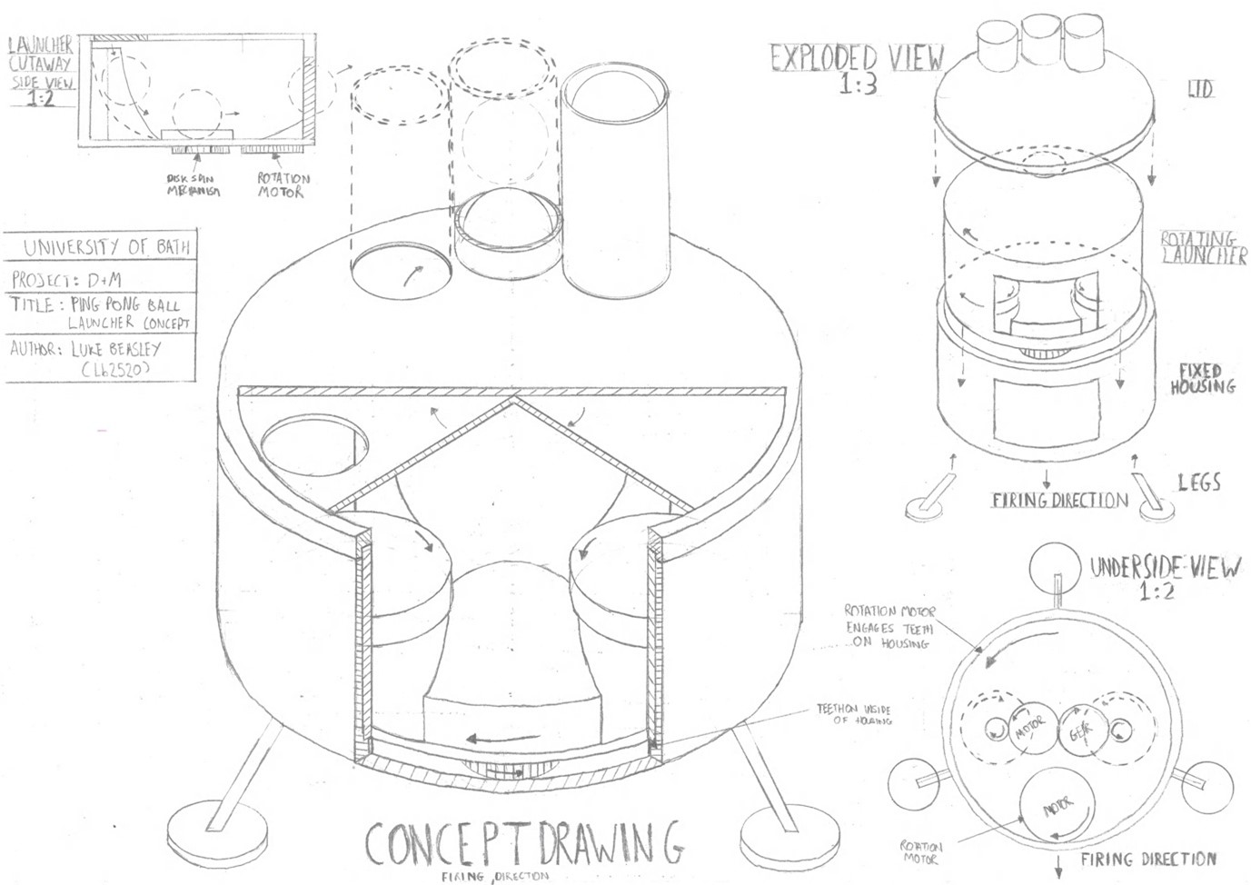
Looking back, I’m pretty proud of this drawing (but I’m definitely glad my drawing skills have developed), and in particular the exploded and cutaway views - I feel like they help demonstrate the concept well. However I certainly could have spent more time on the little things - tidying up my lines, text, and erasing construction lines. I was pleased with my concept too - a rotating launch section within a 3D printed casing. With an appropriately sized hole above the right place in the launch assembly, the launcher would be forced to fire a single ball in the right direction at the right time, adding simplicity to the launch process. This concept would also be quite simple to manufacture and construct, with few separate parts. The snap-on legs and wide base would also minimise the movement of the prototype, and improve its stability.
Design Development
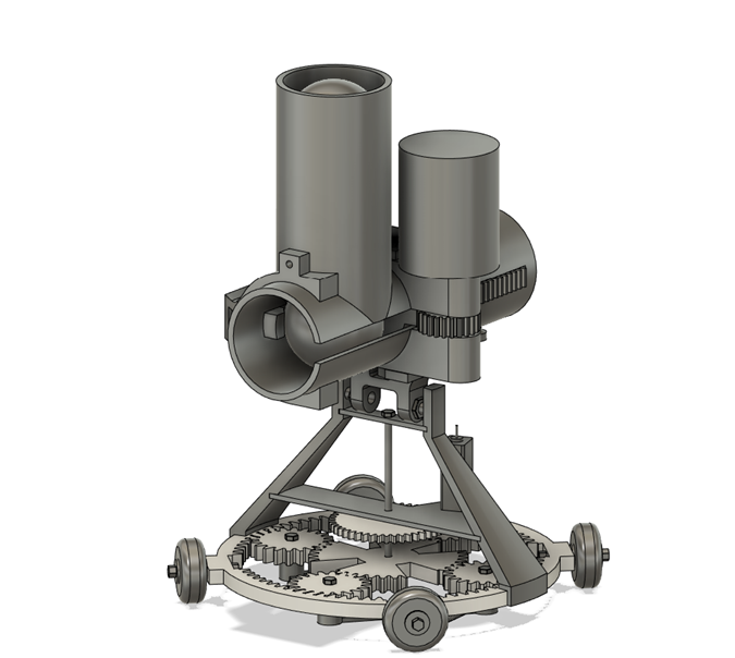
However, this concept had a flaw which we were all aware of from the outset - we were unsure that a spinning disk based design would actually be able launch a table tennis ball reliably. We were also unsure whether these disks would need to be made of foam or be spring-loaded to allow the ball to pass between them. Again, we were encouraged to try things that might not work to provoke discussion, however, we had to go with a launch concept we would be more confident would work as we’d have no opportunity to rectify any mistakes. We finally settled on a spring-loaded plunger design for launching the ball. However, after a few late nights trying to work out the spring specifications to launch the ball appropriately, (not taking into account barrel friction, aerodynamic effects, and a lack of availability of springs), I concluded it would be a safer bet to instead include attachment points for elastic bands, which we could stack up to increase launch power. In theory, we could then test a working set of elastic bands to help devise a spring in future work. The lower portion had a clever planetary gear system that would be spring-loaded to point the launcher in the right direction. You can see the final CAD model below, developed by O. Barker and R. Chan.
The Build
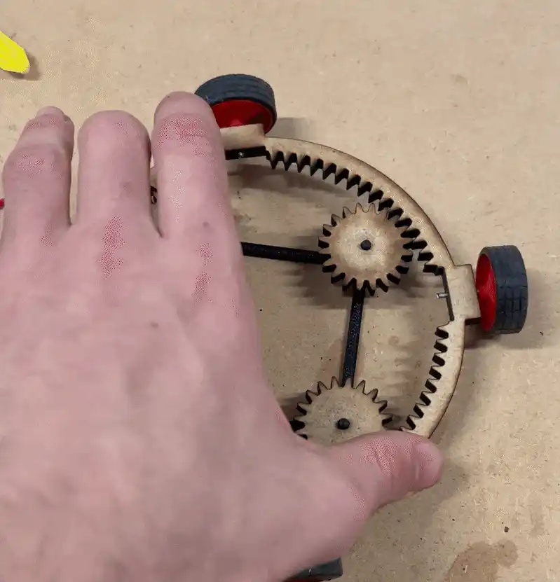
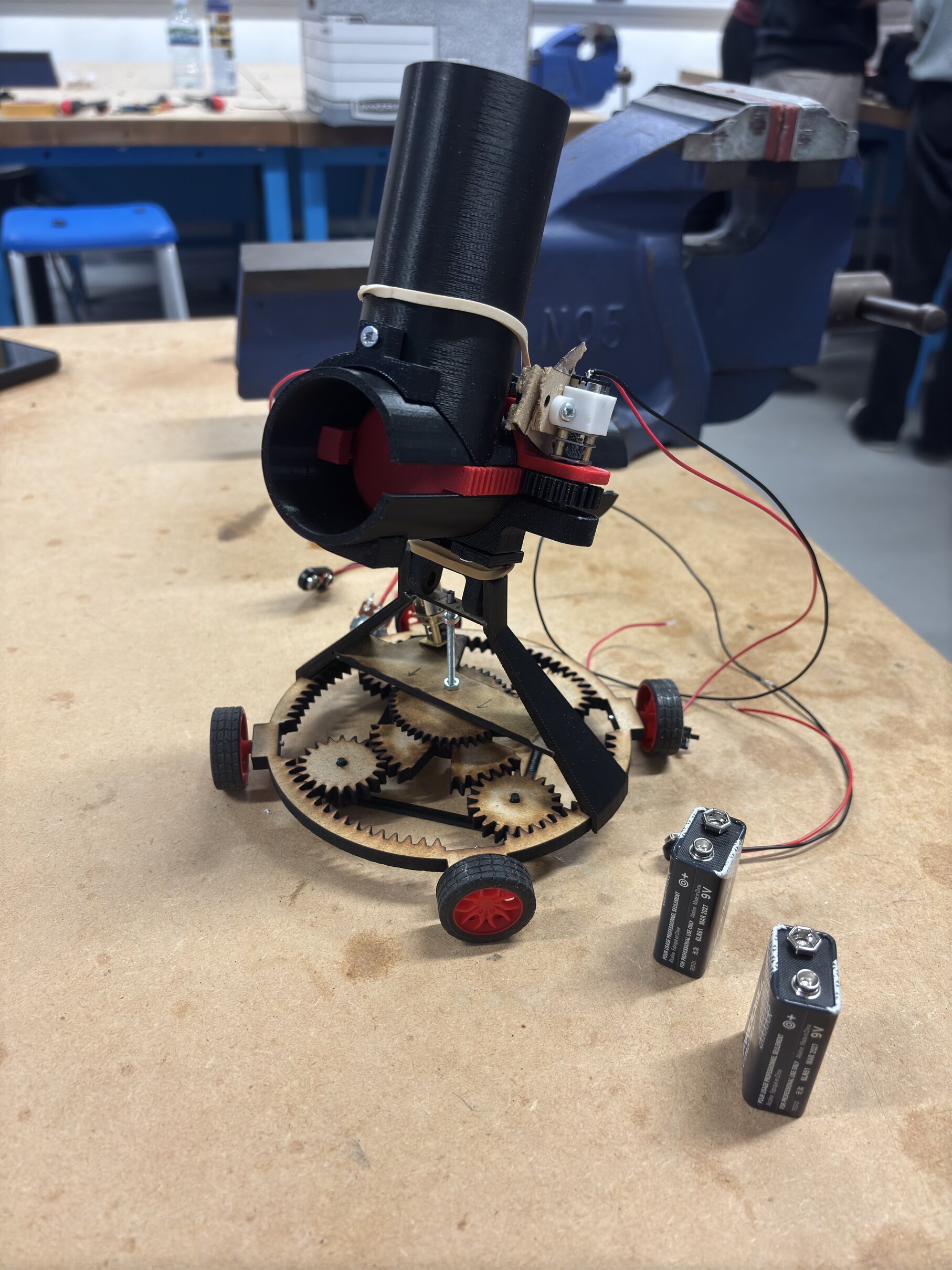
Build Day actually came along at the start of year two, so there was a fair wait between design and make. This led to us having to spend some time reviewing our technical drawings to remember how to build the launcher! You can see the partially-assembled laser-cut planetary gear system below - it worked surprisingly well!
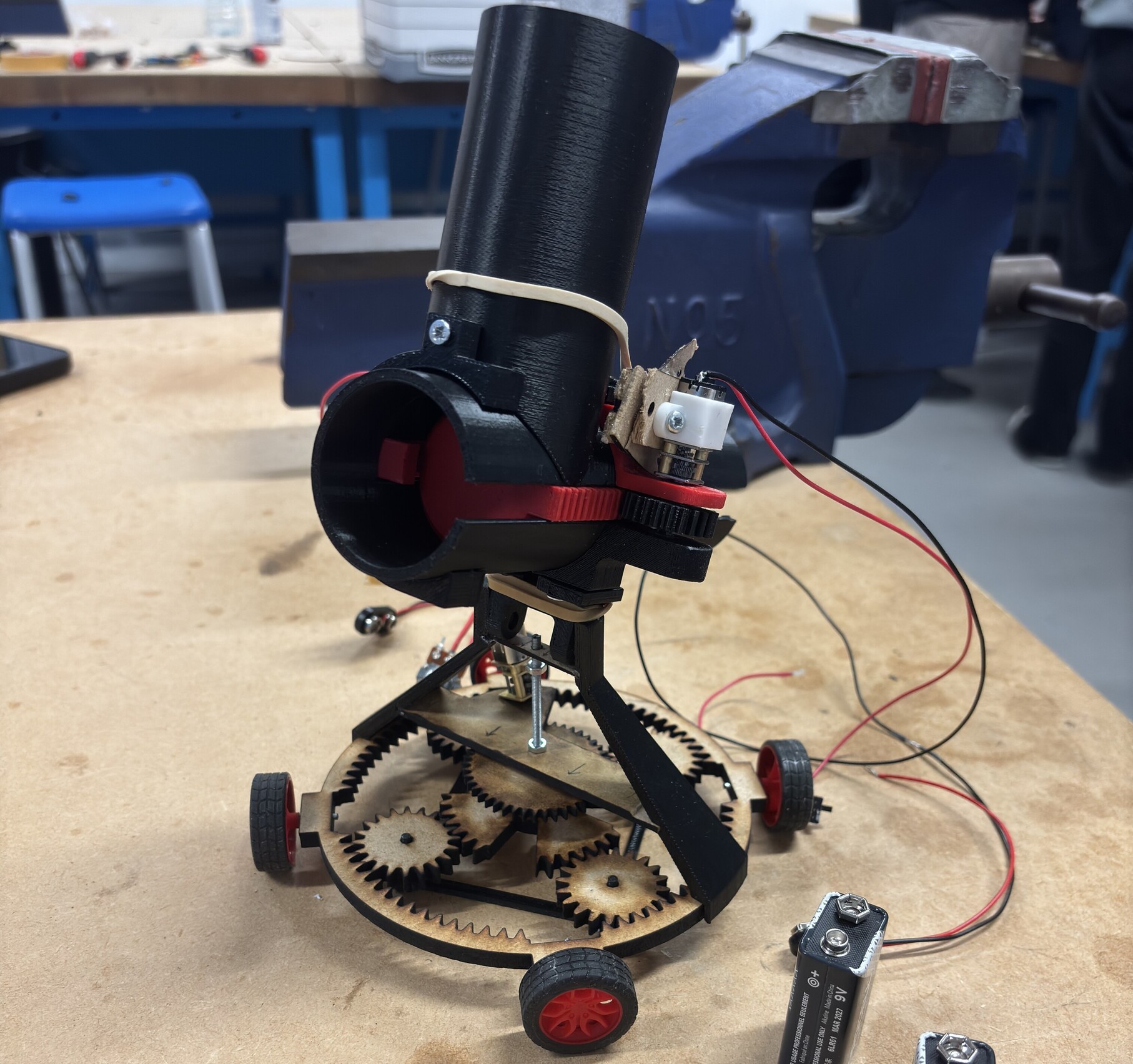
It took a good while to finish the build, as we ran into numerous unforeseen issues (more on that later), but it turned out looking great. Look closely, and you can see many workarounds we had to make compared to the CAD model.
Successes of Build Day
The launch system worked (after a lot of extra effort, again, more on that later)!
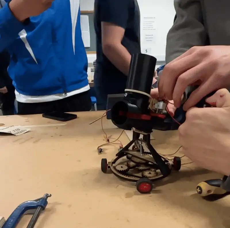
The prototype could load a ball into the firing chamber where it would be locked in place until it was launched with sufficient velocity by the elastic-band loaded plunger, which would retract after firing. The next ball could then fall into place out of the built-in magazine. The prototype also met the size criteria set out in the brief. Here’s a GIF of some trial and error to work out the right number of elastic bands (in this case, not enough).
Issues on Build Day
We were able to fix many unforeseen issues on Build Day:
- Mounting hardware was missing for the launch motor.
- Some laser cut parts were too small.
- The plunger retention pin was too large, blocking the ball.
- High friction was experienced in the launch tube causing unpredictable, noisy launch behaviour.
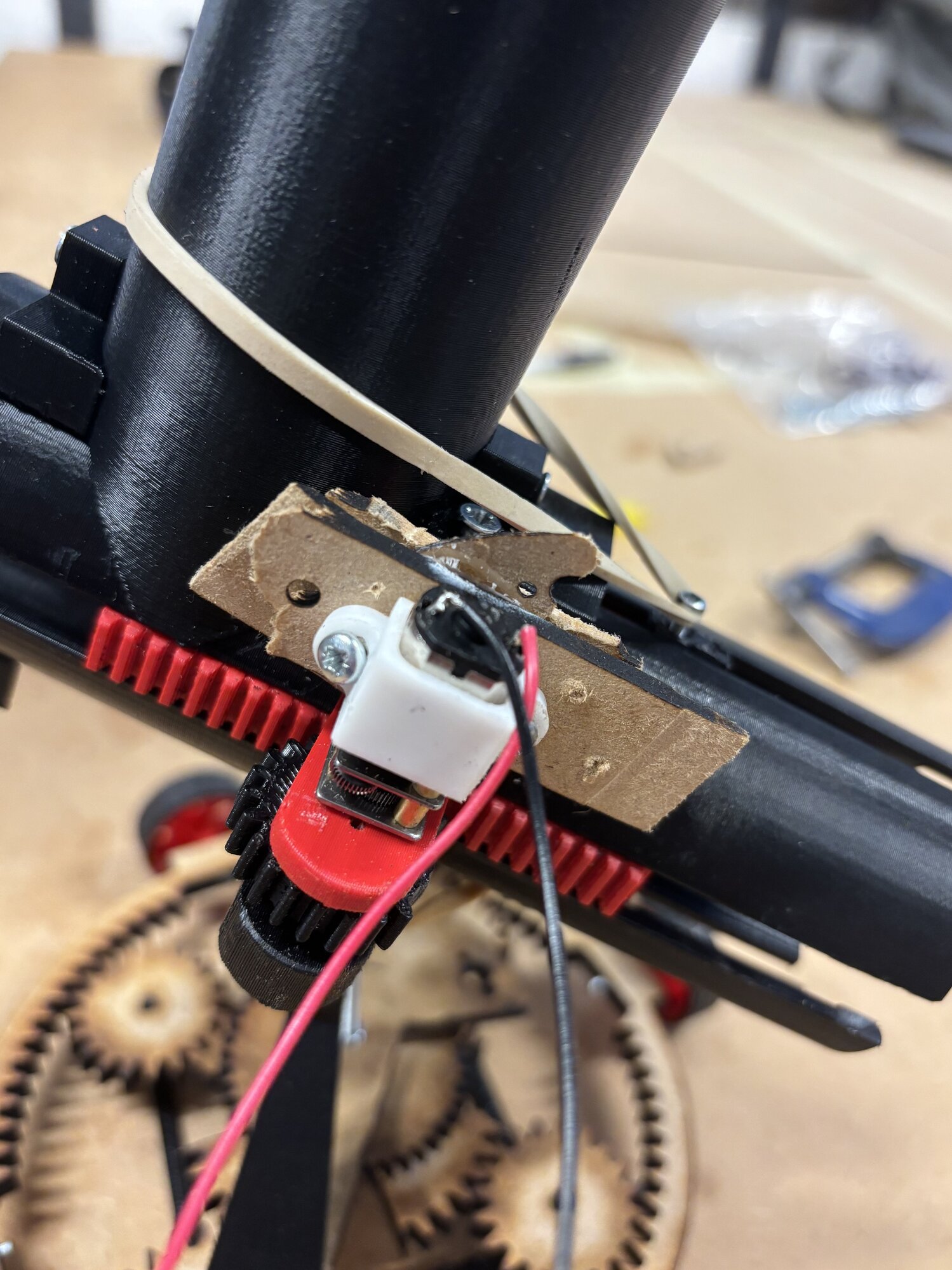
- 3D printed cog in the launch system couldn’t handle the torque induced by the elastic bands, and didn’t work correctly. To fix the launch motor, we had to jerryrig our own mount using a copious amount of MDF and screws. It actually ended up working quite well! However, with the loads experienced in this area of the build, and the precise tolerances needed, this workaround reduced the reliablity and performance of the launch system. You can see the workaround below.
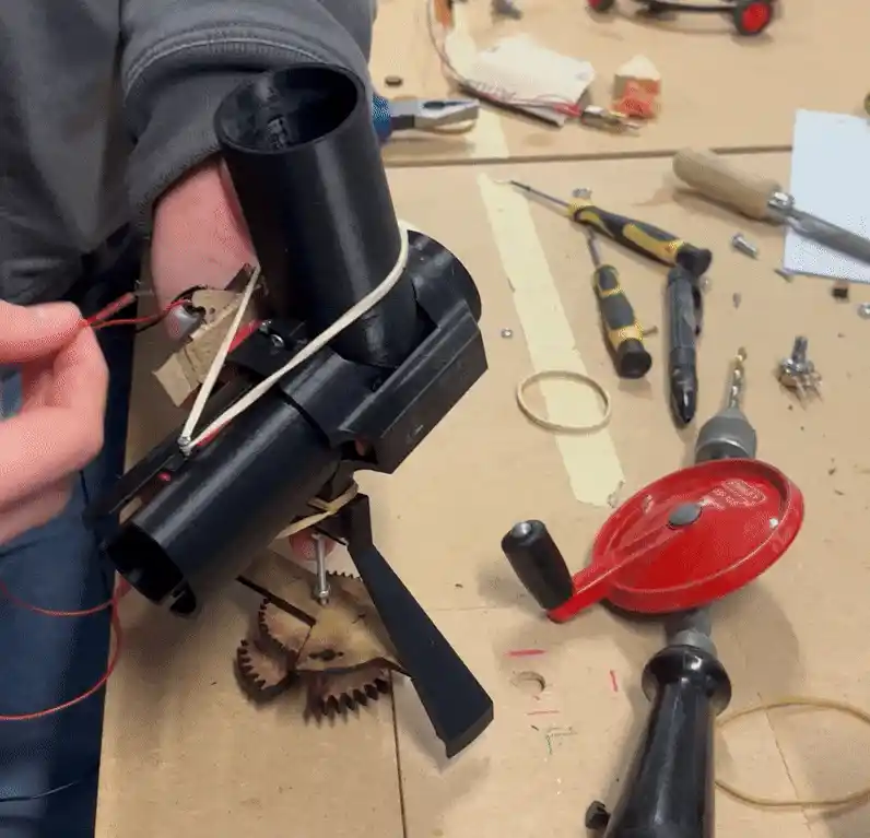
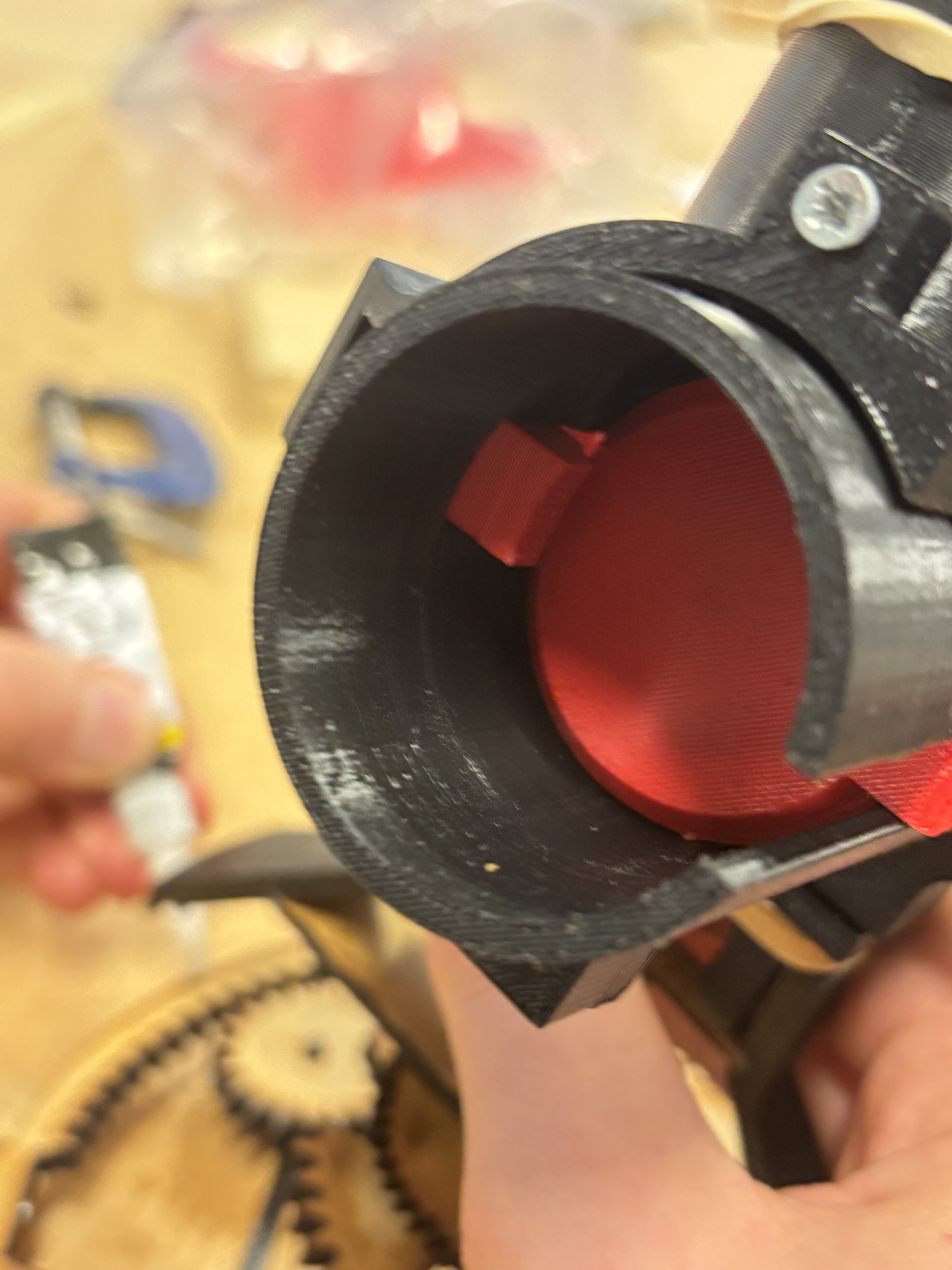
To fix the laser cut part issues, we simply recut them - it turned out there was a formatting issue with the print process. Pretty quick fix, but a holdup nonetheless. Another issue was the plunger retention pin blocking the ball - this was designed to be spring loaded to stop the ball moving in the launch tube during the launch process. However, the springs were stiffer than anticipated and was larger when compressed than expected. A simple fix was to file down the retention pin, which took considerable time and effort (especially when the retention pin had already been carefully installed). We also had to take care to not reduce the size of the pin too much to avoid it failing completely. You can see the results below.
To reduce high launch tube friction, we used plenty of lubricant and tried our best to rectify any misalignments in the system, including by filing down the launch plunger. Lastly, the 3D printed cog in the rack and pinion system ended up threading almost immediately. We got permission to use some glue to fix this. Also, the partial aspect of the gear didn’t work correctly - we just had to cut some extra teeth off.
We were not able to fix certain issues - notably that key parts for the turning hardware did not arrive, including springs and motor mounts. In reality, this was an easy fix as we just had to get in contact with the manufacturers, but in all honesty, I’m not sure we could have completed this system on the day in time even if we had the parts, as most of the day was spent fixing problems and getting at least partial functionality.
Conclusion
Overall, a great project, and the learnings from this project were key going into further second year design projects. The constriction of not being able to iterate actually really demonstrated the benefits of iterative design - for instance it would have been nice if we could make cheaper versions of individual parts to test out first. Working as a team was great - each of us had our own unique strengths and weaknesses and I found that helping to direct the team, jumping in to help team-members that were struggling, and getting the supporting documentation bulletproof was the most effective use of my time. We got a high 2:1 - a fantastic mark that showed our documentation was on point, and that our tenacity in getting partial functionality was worth it. Well done team!